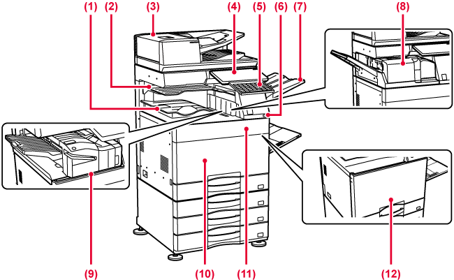
Received faxes and printed papers are delivered to this tray.
Output is delivered to this tray. You can also output jobs to the job separator (center tray) when a relay unit is installed.
It automatically feeds and scans multiple originals. 2-sided originals can be automatically scanned. For the BP-70C31/BP-70C36/BP-70C45/BP-70C55/BP-70C65 both sides of 2-sided originals can be automatically scanned at one time.
This panel hosts
the [Power] button, Information indicator and touch panel.
Use the touch panel to operate each of these functions.
An NFC touch point area mark also appears.
Use this as a substitute
for the soft keyboard displayed on the touch panel. When not being
used, it can be stored under the operation panel.
This is used to connect
a USB device such as a USB memory device to the machine.
Supports USB 2.0 (Hi-Speed).
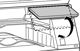
Set this tray as
the output tray if needed.
This folds and outputs
paper.
This staples paper.
A punch module can also be installed to punch holes in output paper.
You can also perform stapling manually.
Open to switch the
main power switch to "On" or "Off".
Open to replace a
toner cartridge.
Open this cover to
switch the main power switch to "On" or "Off" to replace a toner
cartridge.
* Peripheral device.
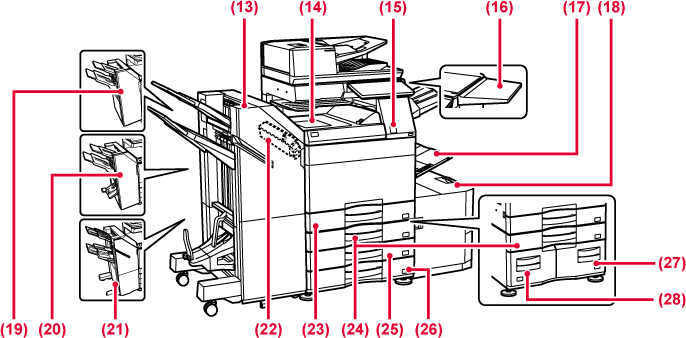
This staples and
folds paper.
A punch module can also be installed to punch holes
in output paper.
You can also perform stapling manually.
Relay between the
machine and the finisher, finisher (large stacker), saddle stitch
finisher or saddle stitch finisher (large stacker).
This sensor detects
the presence of a person that approaches the machine, and automatically
wakes the machine from sleep mode. (Motion Sensor Mode Only)
You can use this
as a work platform, or temporarily place originals or a mobile device.
Caution
Use this tray to
feed paper manually.
When loading paper larger than 8-1/2" x 11"R or
A4R, pull out the extension guide.
Store paper in this
tray.
LOADING PAPER IN THE LARGE-CAPACITY TRAY (when a large capacity tray is installed)
This staples paper.
A punch module can also be installed to punch holes in output paper.
This staples and
folds paper. A punch module can also be installed to punch holes
in output paper.
This staples paper.
A punch module can also be installed to punch holes in output paper.
You can also perform stapling manually.
This is used to punch
holes in output. Requires an inner finisher, finisher, finisher
(large stacker), saddle stitch finisher or saddle stitch finisher
(large stacker).
Store paper in this
tray.
TRAY 1 - 4 (when a stand/550/2x550/3x550/ 550&2100 sheet paper drawer is installed)
Store paper in this
tray.
TRAY 1 - 4 (when a stand/550/2x550/3x550/ 550&2100 sheet paper drawer is installed)
Store paper in this
tray.
TRAY 1 - 4 (when a stand/550/2x550/3x550/ 550&2100 sheet paper drawer is installed)
Store paper in this tray.
TRAY 1 - 4 (when a stand/550/2x550/3x550/ 550&2100 sheet paper drawer is installed)
Store paper in this
tray.
TRAY 3 - 4 (when a stand/550&2100 sheet paper drawer is installed)
Store paper in this
tray.
TRAY 3 - 4 (when a stand/550&2100 sheet paper drawer is installed)
*1 Peripheral device.
*2 This device can only be equipped on the BP-70C31/BP-70C36/BP-70C45/BP-70C55/BP-70C65.
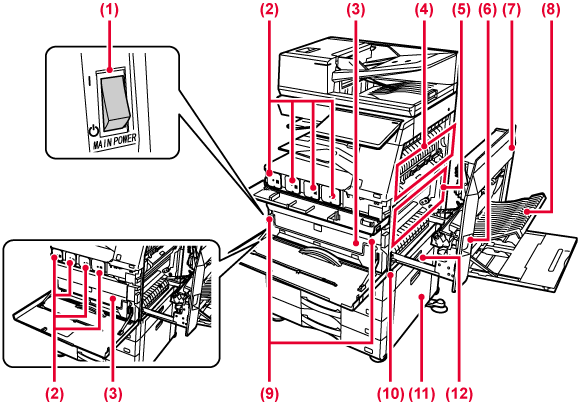
Use this switch to
turn on the power for the machine.
When using the fax or Internet fax functions, always
keep this switch in the “
 ” position.
This cartridge contains
toner.
When the toner in a cartridge runs out, replace
with new one.
This container collects
excess toner that remains after printing.
REPLACING THE TONER COLLECTION CONTAINER
Heat is applied here
to fuse the transferred image onto the paper.
Warning
The fusing unit is hot.During full color printing,
the toner images of the four colors on the photoconductive
drums are combined together on the transfer belt.
During black and white printing, only the black
toner image is transferred onto the transfer belt.
Caution
Do not touch or damage the transfer belt.To remove a paper
misfeed, pull and hold this lever up to open the right side cover.
Open this cover to
remove a paper misfeed.
This unit is used
for reversing paper when 2-sided printing is performed. Open this
cover to remove a paper misfeed.
Press this button
when you need to release the Toner collection container lock to
replace the Toner collection container.
Pull this out and
grasp it when moving the machine.
Open this to remove
a paper misfeed in tray 2, 3 and 4.
Open this to remove
a paper misfeed in tray 1.
BP-50C26/BP-50C31/BP-50C36/BP-50C45/BP-50C55/BP-50C65
BP-70C31/BP-70C36/BP-70C45/BP-70C55/BP-70C65
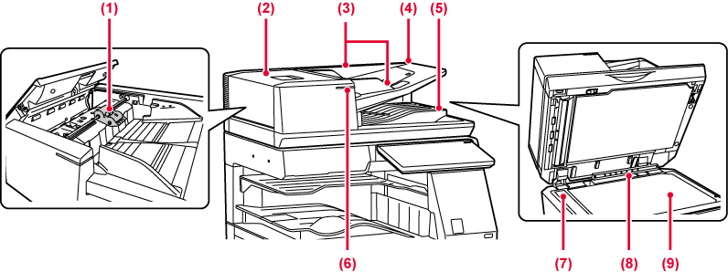
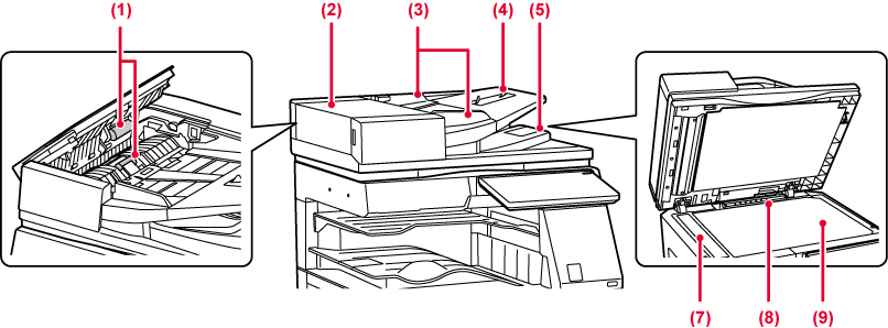
This roller rotates
to automatically feed the original.
Open this cover to
remove an original misfeed.
This cover is also opened to clean the paper feed
roller.
These guides help
ensure that the original is scanned correctly.
Adjust the guides to the width of the original.
Place the original.
Place the original with the print side facing up.
The original is discharged
to this tray after scanning.
This indicator lights when the document is correctly loaded on the document feeder tray.
Originals placed
in the automatic document feeder are scanned here.
This unit detects
the size of an original placed on the document glass.
If you want to scan books or other thick originals that cannot be fed through the automatic document feeder, place them on this glass.
.png)
When the fax function
of the machine is used, an external phone can be connected to this
jack.
When the fax function
of the machine is used, the telephone line is connected to this
jack.
This is used to connect
a USB device such as a USB memory device to the machine.
Supports USB 2.0 (Hi-Speed) and USB3.0 (SuperSpeed).
The machine does
not use this connector.
Connect the LAN cable
to this connector when the machine is used on a network.
Use a shielded LAN cable.
* Peripheral device
This section describes the
names and functions of the respective parts of the operation panel.
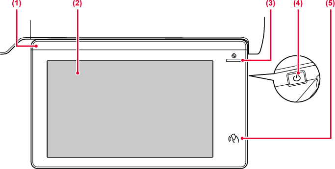
This indicator illuminates
when the power to the machine is turned on, and when a user logs
in to the machine.
Messages and keys
appear on the touch panel display.
Operate the machine by directly tapping the displayed keys.
This indicator lights
up when the machine's main power switch is in the “
” position.
Blinks blue during the time that the [Power] button
does not operate immediately after the main power switch is switched
on.
This indicator will also blink blue when receiving
printer data.
This indicator blinks yellow during Auto Power Shut-Off mode.
Use this button to turn the machine on and off and to enter the power saving mode.
NFC can be used when connecting to Synappx Go. For more information, see the Synappx Go manual
Caution
When turning the machine power ON/OFF; at
user authentication when the user has logged in using IC card or
NFC; when connecting USB memory to the machine; when starting a
job on the machine control panel; or during image adjustment or
when adding toner; a fax is being received or an error has occurred
in the machine, the LED lights blue, white and orange in response
to the request/operation from the user to communicate to the user
the machine status.
Lighting patterns differ depending on status.
| Lighting color | Lighting patterns | Status |
|---|---|---|
|
Blue |
Lighting pattern 1 |
When the power is turned on by user operation or motion sensor, when the power is turned off by user operation, when the power is restored from sleep mode*1, when the power is shifted to sleep mode*1, and when a job (copy, scan, fax) is started by the operation panel. |
|
Lighting pattern 2 |
During user authentication, at user login using an IC card or NFC Insertion of USB memory into the machine |
|
|
Lighting pattern 3 |
When users are made to wait, during image quality adjustment or adding toner |
|
|
White |
Blinks |
A fax is being received. when the job separator (upper tray) or exit tray unit (right tray) is used for output, this blinks until the output is removed. |
|
Orange |
Lights*2 |
Errors that do not stop machine operation, such as replacement timing of the toner collection container. |
|
Blinks*2 |
Errors that stop machine operation, such as misfeeds and out of toner. |
*1 The information lamp lights up when the power is turned on or off directly by the user, or when the machine is restored from sleep mode. The information lamp does not light up when the printer is not operated directly by the user, such as when receiving a print job or when the scheduled auto power shut-off is turned on or off.
*2 If the lighting state and the blinking state overlap, the blinking state takes priority.
Lighting
pattern 1
After lighting sporadically, all lights come on together, and
then turn off.


Version 06a / bp70c65_usr_06a_us
